10 Facade Lighting Installation Mistakes That Cost Projects Years of Performance
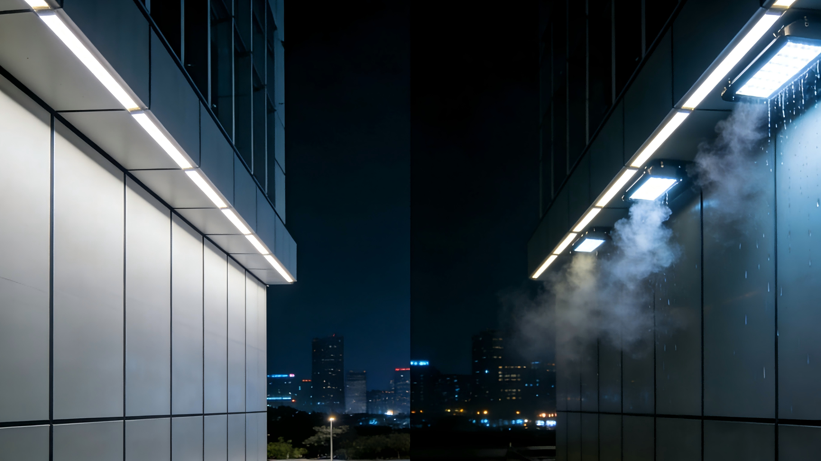
Facade lighting is the "jewelry" of architecture. When executed correctly, it transforms a static building into a nocturnal landmark, defining the skyline and adding immense commercial value. It acts as a visual dialogue between the structure and the city, turning cold stone and glass into a warm, breathing entity after dark.
However, unlike interior lighting, facade luminaires face a brutal, relentless enemy: the outdoor environment. Rain, salt spray, UV radiation, extreme temperature shifts, and wind all conspire to degrade your installation from the moment it is powered on. Many projects fail not because of poor design concepts or low-quality fixtures, but because of installation oversight. A high-end fixture might be rated for 50,000 hours, but a single flawed connection can reduce that lifespan to fewer than 500 hours.
The consequences of poor installation are severe: "zombie" buildings with half-lit sections, astronomical repair costs involving cranes and road closures, and a tarnished reputation for the property. From the first cable run to the final aiming angle, every step demands precision. This article outlines the 10 most critical facade lighting installation mistakes that compromise longevity—and how to avoid them to ensure your project stands the test of time.
1. Neglecting the "Wicking" Effect (Capillary Action)
1.1) The Hidden Killer of Electronics
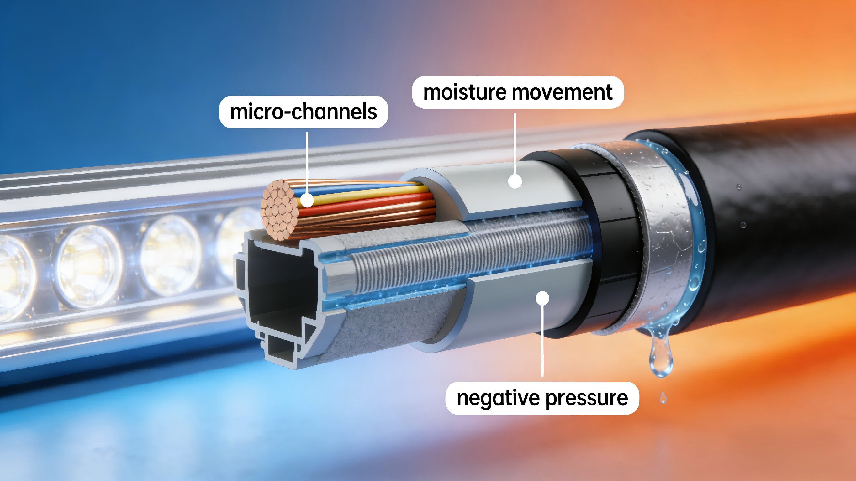
Capillary action in outdoor lighting refers to the movement of moisture along micro-channels inside the cable assembly and conductor strands, driven by pressure and temperature cycles. If a cable gland or joint is not hermetically sealed, that negative pressure draws water into the cable jacket. Moisture then migrates along microscopic gaps in the cable jacket and conductor strands and can travel meters from the entry point.
1.2) What this causes (consequences)
When moisture reaches sensitive electronics it causes corrosion, electrochemical migration, insulation breakdown and intermittent or permanent driver/LED failures. These faults usually appear months later, are hard to trace, and often require wholesale replacement rather than simple repairs.
1.3) Layered Sealing and Verification
Preventing capillary action requires a layered sealing strategy, not reliance on a single waterproof measure. Use resin- or gel-filled joints with true IP68 external connectors, and apply adhesive-lined (dual-wall) heat-shrink and potting at all terminations to eliminate micro moisture paths. Cable routing must include drip loops, with entry glands positioned above the loop’s lowest point, and drivers should be installed in separate sealed enclosures where possible.
Sealing performance must be verified through soak or pressure testing and careful visual inspection during QA. The wicking effect is subtle but destructive—once moisture migrates along conductors, failures often appear months later and are difficult to trace.
2. Ignoring Voltage Drop on Long Runs
2.1) The Visible Gradient of Failure
Facade lighting often involves long linear runs to outline skyscrapers or cornices. A frequent error occurs when installers chain too many fixtures together or use wire gauges that are too thin for the distance. The result is voltage drop: lights at the beginning of the run are bright, while those at the end appear significantly dimmer.
2.2) Color Shift Consequences
Reduced voltage produces visible dimming and non-uniform luminance across the façade and may induce color shifts (white LEDs appearing pinker or warmer). Prolonged undervoltage stresses drivers and LEDs, accelerating lumen depreciation and shortening component life. These problems are immediately apparent in finished installations and costly to rectify.
2.3) Design First: Locking in Performance Through Calculation and Planning
The foundation is accurate calculation and explicit specification. During the drawing phase, mandatory voltage-drop calculations must be performed to ensure the voltage loss at the last fixture in each circuit does not exceed 3%. These calculations should be translated directly into enforceable drawing notes, such as maximum allowable run lengths or minimum cable cross-sections (for example: “For this 24V circuit extended to 50 meters, a 6 mm² cable is required”).
Equally critical is the strategy of segmented power supply or power injection. Long façades should never be powered from a single feed point. Two engineering approaches are recommended:
Segmented power supply: divide long runs into multiple shorter circuits, each independently powered and compliant with voltage-drop limits.
Power injection: for continuous linear installations that must remain electrically continuous, define power injection points at regular intervals (typically every 15–25 meters) in the drawings. Like fuel stations along a highway, these injection points replenish power mid-run to ensure uniform brightness from start to end.
Finally, all requirements—including cable specifications, injection point locations, and circuit segmentation—must be clearly documented in the construction drawings. This is the only reliable way to convert a potential quality risk into a controlled installation process, ensuring first-time compliance and avoiding costly post-installation rework.
3. Ignoring Driver Lifetime, Protection, and Maintainability
3.1) The Reality of Driver Lifespan
Although LED light sources can operate reliably for a decade or more, their power supplies (drivers) typically have a much shorter service life and are the most failure-prone electronic component in the system. Heat, load stress, moisture, and electrical surges all accelerate driver aging. Treating drivers as long-life components comparable to LEDs—and permanently embedding them in inaccessible locations—is a fundamental planning error.
3.2) Driver Protection
Choosing drivers with insufficient ingress protection (for example, below IP65) or without effective built-in surge protection devices (SPDs) in order to reduce cost is another critical error. In harsh façade environments, dust and moisture ingress can lead to internal corrosion and short circuits, while lightning strikes or grid fluctuations generate surge currents that can instantly destroy sensitive electronic components, causing large-scale system failure.
3.3) Driver Installation Location
The most costly mistake is installing drivers in inaccessible locations—such as sealed within aluminum façade panels, cast into concrete structures, or hidden behind decorative finishes without service access. In such cases, replacing a driver worth only a few dozen dollars may require aerial lifts, scaffolding, or even demolition of façade elements, resulting in maintenance costs of thousands or even tens of thousands of dollars. This is the classic scenario of “using a crane to replace a capacitor.”
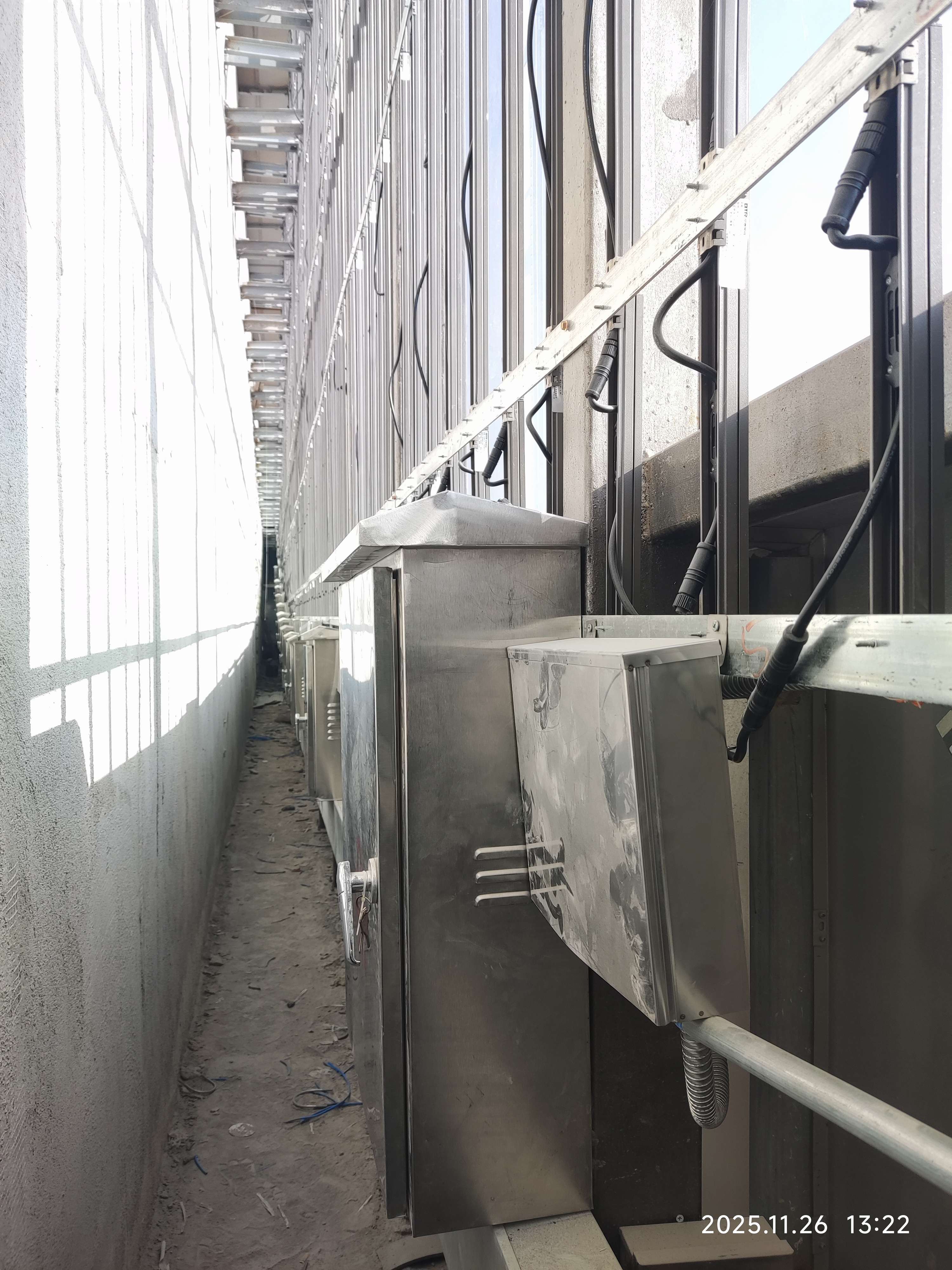
3.4) Protection and Centralized Power Strategy
Best practice is to house drivers in centralized, well-ventilated, and easily accessible cabinets—such as rooftop equipment rooms, catwalks, or dedicated control spaces—where they can be protected from moisture, dust, and thermal stress. When local installation is unavoidable, drivers must be adequately rated for outdoor conditions and paired with discreet but practical access hatches. Designing for protection and access at the outset ensures that inevitable driver replacements remain simple, safe, and cost-effective rather than disruptive and expensive.
4. Overlooking Galvanic Corrosion
4.1) How Dissimilar Metals Form a “Corrosion Battery”
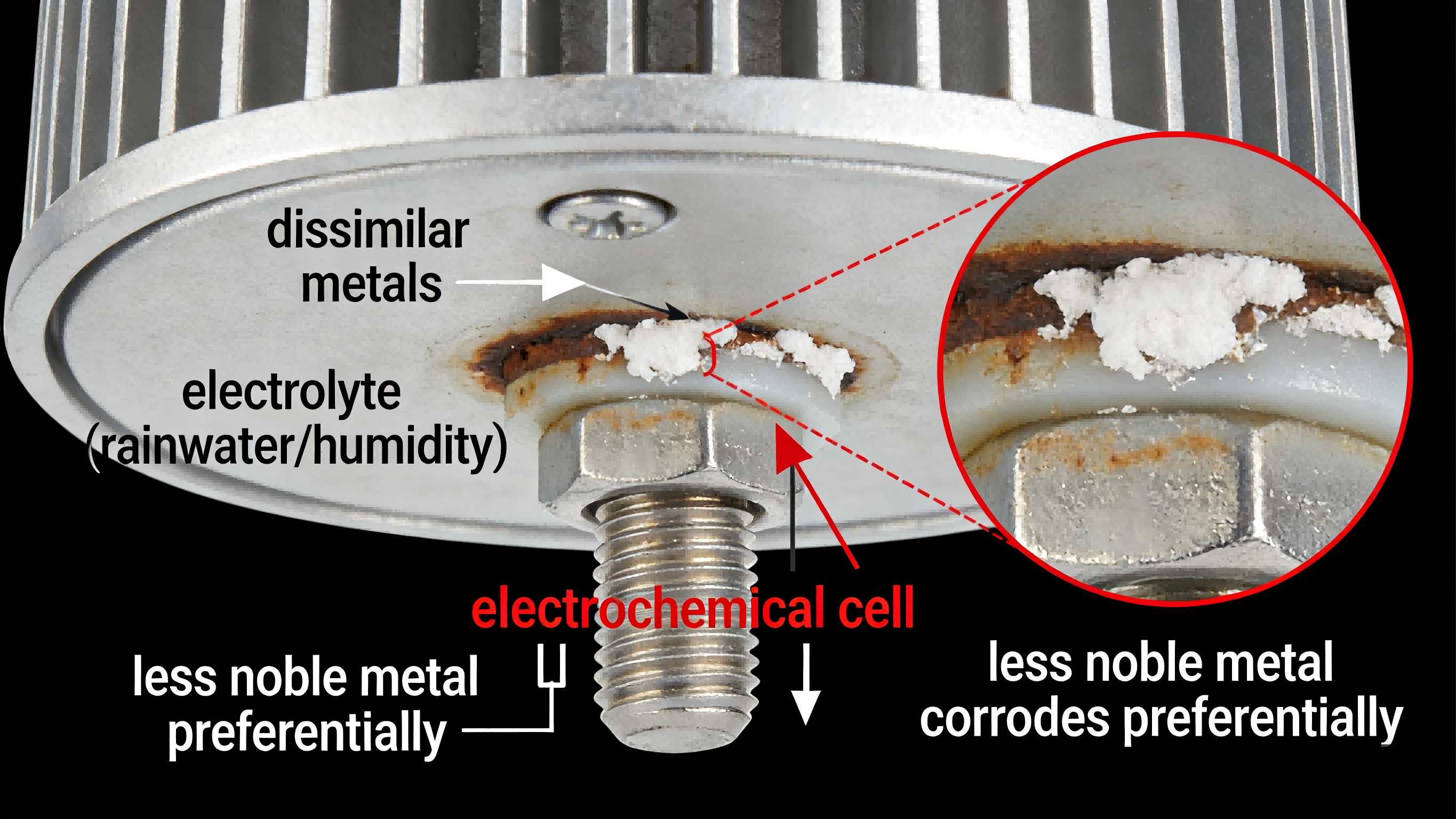
Galvanic corrosion occurs when two dissimilar metals are in direct electrical contact in the presence of an electrolyte such as rainwater, humidity, or salt spray. This creates an electrochemical cell in which the less noble metal corrodes preferentially, often at an accelerated rate. In outdoor lighting installations, this process is continuous and unavoidable once incompatible materials are paired.
4.2) From Fastener Failure to System Collapse
Improper material pairing—such as zinc-plated or carbon steel fasteners used with aluminum fixture housings or brackets—leads to rapid corrosion at the contact points. Over time, fasteners may seize or fuse to the fixture body, brackets can weaken or fracture, and load-bearing integrity is compromised. Maintenance becomes extremely difficult or impossible, turning routine servicing into destructive work that risks damaging the façade or the luminaire itself.
4.3) Practical prevention through material selection and isolation
Preventing galvanic corrosion requires deliberate material and installation choices. For outdoor architectural lighting, mounting hardware should be 316-grade stainless steel, particularly in coastal or high-humidity environments. Electrical isolation should be introduced wherever possible using nylon or polymer washers, gaskets, or bushings to break metal-to-metal contact. Anti-seize compounds and protective coatings further reduce the risk of bonding and corrosion, ensuring both long-term structural stability and serviceability.
By treating material compatibility as an engineering requirement rather than a minor detail, galvanic corrosion can be effectively controlled before it compromises safety, appearance, or maintenance access.
5. Ignoring Thermal Management for Recessed Fixtures
5.1) The Fatal Effect of Heat Buildup: When the Fixture Becomes an “Oven”
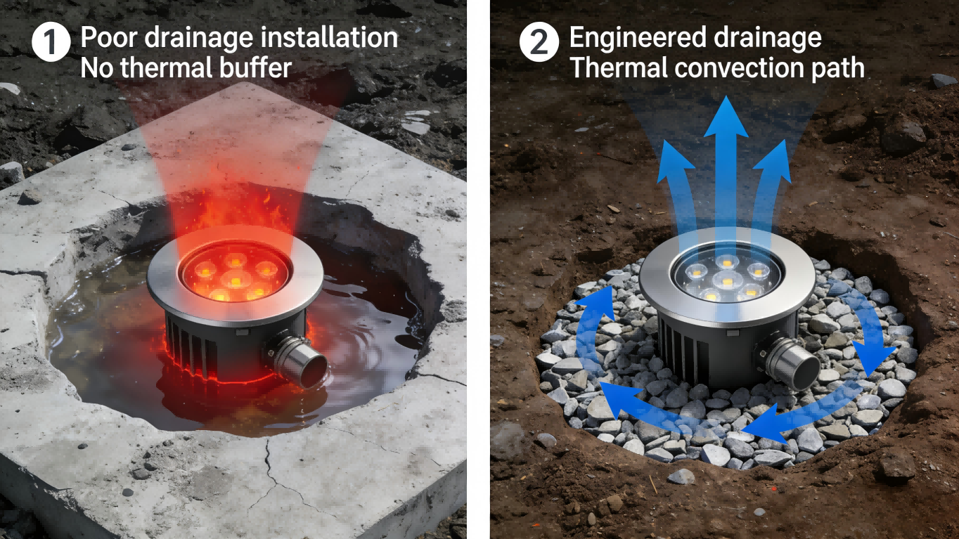
For recessed luminaires—such as inground uplights, step lights, or in-wall linear fixtures—the core challenge is effectively removing heat from a confined installation environment. A typical failure scenario occurs when fixtures are embedded directly into concrete, compacted soil, or airtight structural cavities without any intentional heat-dissipation path, causing internal temperatures to exceed the designed allowable junction limits.
5.2) The Insulating and Corrosive Effects of Water and Debris
Poor thermal management is often compounded by inadequate waterproofing, creating a destructive feedback loop. Standing water acts as an efficient thermal insulator: if base drainage is insufficient, rainwater or condensation accumulates around the fixture, severely restricting heat dissipation into the surrounding soil or air. In addition, accumulated dust and silt provide further insulation, intensifying heat buildup. Sustained high temperatures directly accelerate lumen depreciation, color shift, and premature aging of driver components, ultimately leading to rapid light output loss, flicker, or complete fixture failure.
5.3) Designing Proper Drainage and Heat-Dissipation Paths
Reliable thermal management must be treated as a system-level engineering solution, not merely correct placement. Key measures include:
Constructing a drainage and thermal layer: For inground fixtures, a sufficiently thick gravel bed (typically ≥150 mm) must be installed at the bottom of the pit to serve as both drainage and heat-dissipation base. This allows water to escape quickly and uses the air voids between stones to aid heat transfer.
Mandatory use of manufacturer installation kits: Factory-supplied sleeves or housings are not optional accessories. They are typically engineered with heat-dissipation features, waterproof locking structures, and defined air or thermal paths, forming a critical thermal buffer and mechanical protection interface between the fixture and its environment. Installation must strictly follow manufacturer instructions.
Ensuring airflow: For recessed linear fixtures installed in wall slots, concealed ventilation paths should be planned during the design stage. Avoid fully sealing both ends; instead, use a mild “chimney effect” to encourage air movement and remove heat. Adequate clearance should be maintained between the back of the fixture and the slot structure to prevent direct contact and localized heat buildup.
In practice, effective drainage and heat-dissipation design not only extends fixture lifespan but also safeguards lighting performance and system reliability.
6. Misunderstanding IP Ratings (IP65, IP67, and IP68)
6.1) The Limits of “Waterproof” Claims
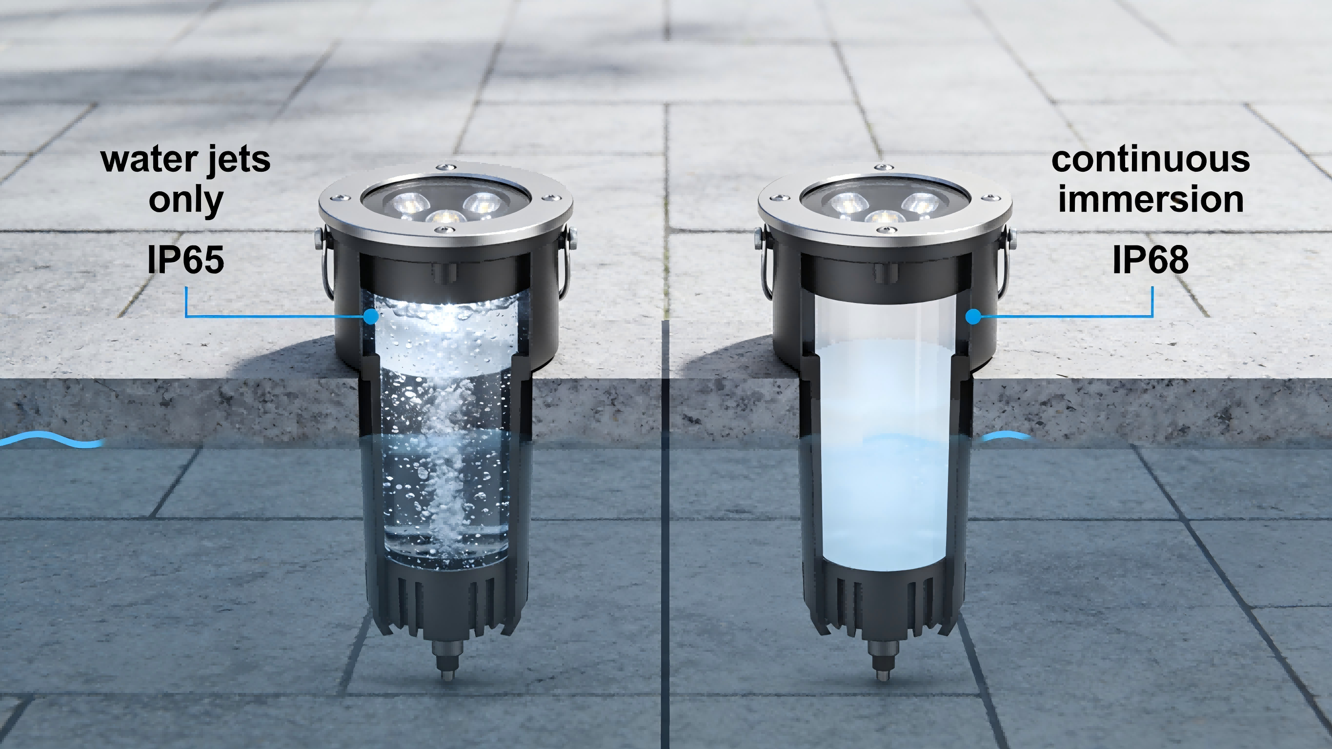
The term “waterproof” in lighting specifications can be misleading and carries risks if misinterpreted. The critical distinction lies in the IP (Ingress Protection) rating, which defines the level of protection against moisture under specific test conditions. An IP65 fixture resists low-pressure water jets from any direction but does not provide protection against immersion or hydrostatic pressure. A fundamental mistake is equating “waterproof” with “submersion-proof,” which exposes the fixture to conditions beyond its intended limits.
6.2) Submersion Risks for Recessed Fixtures
For ground-level, trench, or other recessed applications, the risk extends beyond simple water exposure to include hydrostatic pressure and duration of immersion. If drainage fails or the installation pit accumulates silt or debris, the fixture may become partially or fully submerged for days or even weeks. Prolonged static pressure can stress gaskets and seals beyond their tested limits, creating microscopic paths for water ingress. This can lead to internal condensation, corrosion of drivers and PCBs, and irreversible failures.
6.3) Designing for the Worst-Case Scenario
Robust design requires planning for the most severe possible environmental conditions, including not just rainfall but also irrigation, snowmelt, cleaning processes, and potential drainage blockages. IP68 fixtures are engineered and tested to withstand continuous pressure immersion, with depth and duration defined by the manufacturer (often exceeding 1 meter for extended periods). At the same time, mechanical design must ensure effective drainage around the fixture body and use sealed conduits to prevent water migration along cables into the enclosure.
7. Poor DMX/Data Cabling Practices
7.1) Signal Integrity Issues
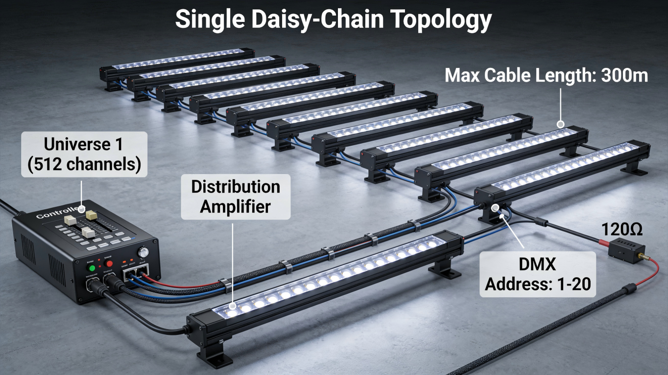
DMX512 (RS-485) is a differential, bus-style protocol that depends on controlled impedance and a single continuous data path. Treating it like a power network and implementing “star” topologies or multiple random branches breaks the bus and creates reflections, timing errors, and lost frames. Common consequences include flicker, color jump, latency, and synchronized failures across many fixtures.
Best practices: always use a single daisy-chain per universe with clearly defined ends; avoid unterminated branches; keep total cable length and per-segment lengths within recommended limits; use distribution amplifiers or DMX splitters when you must fan out to multiple physical locations; and maintain consistent grounding and shield termination to reduce common-mode noise.
7.2) The Wrong Cable Type
In DMX512 data transmission, impedance mismatch can cause signal reflection and attenuation, reducing rise time and leading to data corruption. To ensure reliable signal integrity, manufacturers must use dedicated 120 Ω twisted-pair cables with a continuous ground/shielding layer, low capacitance, and solid copper conductors. For outdoor or buried installations, choose UV-resistant, gel-filled, or cable tray-rated cables, and avoid using cheap, unbranded alternatives.
7.3) Termination Importance
A 120 Ω termination resistor between Data+ and Data− at the physical end of the line absorbs reflections and stabilizes the differential signal. Without termination, reflected pulses interfere with subsequent bits, producing intermittent and hard-to-diagnose errors. When splitting a universe, each physical branch must be properly terminated at its far end (or use active splitters with proper termination). Use fixtures or controllers with accessible termination switches, and verify with a DMX tester or oscilloscope that the line shows clean waveforms and correct idle levels.
8. Failing to Account for Thermal Expansion
8.1) Building Movement
A facade is a dynamic, living skin, not a rigid monolith. All building materials—aluminum, glass, steel, concrete—expand when heated and contract when cooled. This movement is continuous and significant; a 100-meter-long aluminum facade can expand and contract by several centimeters between winter and summer extremes. This cyclical, thermally induced movement is a fundamental, predictable engineering reality. A critical design oversight is treating the lighting system as a static element attached to this dynamic substrate, leading to predictable and catastrophic failures.
8.2) Mechanical Stress on Fixtures
When rigidly fixed linear lighting systems are attached to a moving facade, they are subjected to enormous compressive and tensile forces. Without engineered provisions to accommodate movement, this stress must be absorbed by the weakest components. This results in a predictable cascade of failures: extruded aluminum housings buckle or warp; delicate acrylic or polycarbonate lenses develop stress cracks; mounting brackets shear or pull away from the facade; and internal PCB traces or solder joints fracture from repeated flexing. The failure is not an "if" but a "when," often manifesting within the first few seasonal cycles after installation.
8.3) Flexible Connections
Accommodating thermal movement requires a systematic approach centered on creating "forgiveness" at every connection point. This is not optional but a core engineering requirement. First, installers must meticulously follow the manufacturer’s specified end-to-end expansion gap (typically 3-10mm per standard fixture length) between linear modules. Second, all electrical and mechanical connections between segments must be flexible. This involves using pre-assembled flexible jumper harnesses with service loops, rather than rigid, in-line connectors. Mounting hardware should allow for lateral slide or pivot, using slotted holes or specialized sliding clips. Furthermore, cable management must be designed with ample slack and strain relief at fixation points to prevent conductors from being stretched or sheared. Ignoring these details guarantees that the lighting system will fight the building it is meant to enhance, leading to costly, repetitive repairs.
9. Neglecting Surge Protection
9.1) External Electrical Threats
Outdoor lighting systems are directly exposed to various transient overvoltages (surges). These threats originate not only from the immense energy of direct lightning strikes or nearby lightning strikes, but more commonly from switching operations and the starting and stopping of large equipment within the power grid. The internal electronic components of LED drivers and smart control modules are extremely sensitive, and their built-in basic protection (usually only capable of withstanding 1.5-4kV test waveforms) is very fragile in the harsh electromagnetic environment of the real world. Connecting these precision electronic devices directly to outdoor lines without external protection is equivalent to placing them at continuous electrical risk.
9.2) Catastrophic Systemic Failure
The damage caused by a successful surge attack goes far beyond the failure of a single luminaire. Its destructive path is cascading and systemic: high-voltage surges can propagate along power lines or signal lines, instantly destroying the input filtering circuits and DC/DC conversion modules of multiple drivers; simultaneously, it can damage expensive central controllers, decoders, and dimming modules through common-ground coupling or induction. The consequence is not simply "individual lights going out," but the paralysis of the entire lighting circuit and the burning out of core control equipment.
9.3) Layered Defense Strategy
Effective surge protection must employ a layered (tiered) defense engineering concept, setting up multiple lines of defense along different surge intrusion paths to gradually dissipate and limit the voltage.
First level (coarse protection): Install surge protective devices (SPDs) that meet Class I test requirements (10/350μs waveform) in the main distribution box of the building or the main distribution cabinet of the lighting system to dissipate direct lightning strikes or most of the energy from external lines.
Second level (intermediate protection): Install Class II test (8/20μs waveform) SPDs in the distribution boxes leading to each facade area to further limit the residual voltage after attenuation by the first level.
Third level (fine protection): For particularly important, extra-long, or independent luminaire circuits, and all outdoor data/control signal lines, Class III test SPDs or dedicated signal surge protectors should be installed at the end or at the front of the equipment to provide "last mile" fine protection for the final electrical equipment.
All surge protective devices (SPDs) must have appropriate voltage protection levels (Up values) and ensure extremely low impedance in their grounding path (PE wire) to facilitate rapid energy dissipation. Furthermore, the protector itself should have status indicators and be included in a regular maintenance and inspection plan to ensure its long-term effectiveness.
10. Skipping the “Night Aiming” and Locking Phase
10.1) The Difference Between “On” and “Done”
The final, non-negotiable step in any facade lighting project is professional nighttime commissioning, often referred to as the “night aiming” phase. This is the process where the installed system is meticulously adjusted after dark to realize the design intent captured in renderings and light studies. Relying solely on daytime aiming is a profound error, as the visual impact of light is fundamentally different under actual nighttime conditions. Skipping this step means accepting a generic “on” state over a curated “performance,” often resulting in a disorganized wash of light that fails to articulate the architecture.
10.2) Light Pollution and Glare
Precise aiming is the primary technical tool for controlling light pollution, light trespass, and disability glare. Without it, fixtures intended to graze a textured wall will instead project a broad, uncontrolled spill into the night sky. Up-lights meant to accent a parapet will blast directly into the windows of upper floors, creating discomfort for occupants and violating lighting ordinances. The aesthetic consequence is equally damaging: beam patterns will fail to cleanly align with architectural lines, creating overlapping pools of light, hard “cut-offs” in the wrong places, and a generally “sloppy” visual appearance.
10.3) Mechanical Locking
The precision achieved during night aiming is ephemeral unless it is permanently secured. Every adjustable fixture—spotlights, grazing units, framing projectors—incorporates a locking mechanism, typically set screws or lock nuts. A critical installation failure is neglecting to methodically tighten all locking hardware once the perfect aim is confirmed. Over time, the cumulative effects of wind vibration, thermal cycling, and incidental contact will cause inadequately locked fixtures to slowly drift from their set position. This drift, often imperceptible day-to-day, leads to the gradual but total degradation of the designed lighting scheme within months. Therefore, the commissioning protocol must explicitly include a documented “lock-down” procedure, treating it with the same discipline as the aiming itself, to ensure the design remains intact for the life of the installation.
Facade lighting’s success depends as much on installation discipline as on good design and quality fixtures. The ten mistakes above are common, largely avoidable, and usually stem from treating installation details as afterthoughts rather than contract requirements. To secure durable, high-performance results, embed engineering-led specifications, layered protection, and rigorous QA (seal/soak tests, voltage checks, surge strategy, night aiming and mechanical locking, and lifecycle maintenance planning) into drawings, contracts, and commissioning procedures.
Conclusion
Facade lighting’s success depends as much on installation discipline as on good design and quality fixtures. The ten mistakes above are common, largely avoidable, and usually stem from treating installation details as afterthoughts rather than contract requirements. To secure durable, high-performance results, embed engineering-led specifications, layered protection, and rigorous QA (seal/soak tests, voltage checks, surge strategy, night aiming and mechanical locking, and lifecycle maintenance planning) into drawings, contracts, and commissioning procedures. If you’d like, I can convert this into a one-page installation checklist, a commissioning protocol, or a contractor punch-list you can use on site.
About LNJAMI
At LNJAMI, we specialize in outdoor architectural and facade lighting solutions engineered for long-term performance, not just visual impact. Since 2008, we have supported global projects with a deep understanding that lighting success depends as much on installation discipline, material compatibility, thermal management, and electrical protection as on fixture quality itself. From linear facade lighting and wall washers to bridge and landscape illumination, our products and technical support are designed around real-world installation challenges—voltage drop, moisture ingress, corrosion, thermal expansion, data integrity, and surge protection. By combining robust luminaire design with clear installation guidance, system-level thinking, and project-specific support, we help designers, contractors, and developers deliver facade lighting systems that remain stable, serviceable, and visually precise for years after commissioning.
Frequently Asked Questions
Q1: How do I choose the correct wattage for LED wall washers?
Base wattage on mounting distance, target illuminance (lux), surface reflectance and ambient light. Perform photometric calculations during design phase and prefer balanced output matched to mounting distance rather than simply increasing wattage.
Q2: How should I select beam angle for a given facade?
Match beam angle to mounting height and facade geometry — narrow beams for vertical features and texture grazing, wider beams for broad, even wall coverage. Mock-ups or lighting simulations help confirm coverage and avoid hotspots.
Q3: What is the difference between IP65, IP66, IP67 and IP68, and when should I use each?
IP65 resists water jets and dust (general facade use); IP66 withstands heavy rain/dust (harsher exteriors); IP67 resists short-term immersion (ground-mounted or poor drainage); IP68 is rated for prolonged submersion (flood-prone or highly exposed sites).
Q4: Is DMX512 necessary for my facade project?
Use DMX512 for dynamic color scenes, pixel mapping, synchronized shows or large-scale RGB/RGBW installations requiring precise white tuning. For static white lighting, 0–10V or DALI is often more cost-effective.
Q5: What is the “wicking” (capillary) effect and how do I prevent it?
Wicking is moisture migration along cable micro-paths into electronics. Prevent it with layered sealing: IP68 external connectors, potting/resin or gel-filled joints, adhesive-lined heat-shrink, drip loops and glands positioned above loops; verify by soak/pressure testing.
Q6: How can I avoid voltage drop on long runs?
Calculate allowable voltage drop during design (keep last-fixture drop within project limits, e.g., ≤3%), use appropriate cable gauge, segment power supplies, or define regular power-injection points to maintain uniform brightness.
Q7: Where should LED drivers be installed for best maintainability?
House drivers in centralized, ventilated, accessible cabinets (rooftops, catwalks, dedicated rooms). If local placement is unavoidable, use outdoor-rated drivers, sealed enclosures and accessible service hatches.
Q8: How do I prevent galvanic corrosion between fixtures and fasteners?
Use compatible materials (316 stainless fasteners in coastal/high-humidity areas), introduce electrical isolation (polymer washers/gaskets), apply anti-seize treatments and use protective coatings to break metal-to-metal galvanic paths.